
I’ve written a lot of theory stuff recently, so let’s talk about practical stuff for a bit.
Putting in the big order
After researching online, I found that Farnell was about the best place to buy things. So I created an account, and ordered two items, mostly to see if it worked. Well obviously it did, and I ended up with a bench power supply and some breadboard.
I used the power supply and the existing wires I had to test out some of my LEDs. Well yes, they work. But I can buy a matching set of them for pennies, so there’s not much point struggling on with old, broken stuff.
Having determined that this path seems feasible, I proceeded to put in a much bigger order for… all sorts of stuff. ICs, LEDs, wire, tools, the whole smash. Perplexingly, the most expensive part was the wire. Apparently 100 ICs that have to be manufactured in a UL-certified cleanroom by people walking around in moon-suites is cheaper than 400 meters of plain, ordinary copper wire. Go figure!
So a bunch of stuff turned up at work, and I may have got a little bit over-excited about all my new toys to play with. And then Farnell sent the VAT bill to my employer instead of me, which… wasn’t optimal. From now on, I get stuff ordered to my house.
Breadboard
My initial plan was a buy a bunch of breadboards, jump ICs into them, and some wires, and build myself some circuits. It turns out that, while that does work, it’s quite fiddly getting the wires into and out of the breadboard.
For those that don’t know, this is breadboard:
It’s basically a brick of plastic, with a grid of holes drilled into it. You poke wires into the holes, and metal springs inside the board hold the wire in place. Each row of holes are wired together, but columns aren’t connected in any way. This particular brand of breadboard also has a column of + and − holes along its length. (The red and blue strips.)
As well as breadboard, I bought assorted lengths of jumper wires. (The little grey and orange things.) These in particular really require pliers to insert and remove; they’re so damned fiddly!
In short, I bought a small amount of breadboard and fully intended to buy lots more… but in the end, I never did. I hardly ever use the breadboard I’ve already got, now.
Stripboard
I still have my old soldering iron, and I decided to get some shiny new stripboard. The basic stuff is about £2 per board, so I got several kinds to try them out.
Again, for those who aren’t electronics experts, this is stripboard:
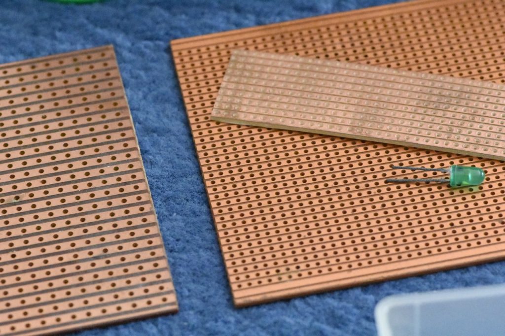
It’s basically a sheet of plastic with strips of copper glued to it on one side, and then holes drilled into it. If you poke a wire or something through a hole, you can then solder the wire to the board. Any wires soldered to the same strip of copper are essentially connected together by the copper strip. You can also use a knife to (crudely) cut the copper strip at various points, making it into multiple seperate pieces which (hopefully) aren’t connected.
Rather than stripboard, what I actually ended up buying was perfboard. That is, like the above, but instead of strips of copper, each hole has a little square of copper around it, but not connected to any neighboring squares. You’re supposed to use solder to bridge the gap. This, it turns out, it easier said than done! Essentially, you can buy stripboard and have the faff of trying to cut tracks, or buy perfboard and have the faff of trying to join squares. I opted for the latter.
An obsession with Eurocard
I don’t remember how I discovered this, but I eventually discovered the “Eurocard” series of standards. Basically a Eurocard is one of several standardised sizes of circuit board that fits into slots in a 19-inch rack, and typically uses a type of connector called DIN-41612. It has been used for things like VMEBus (whatever that is), and various other standards.
Basically, if you do a Google image search for many of these terms, you can back some extremely cool images of very impressive-looking hardware. I have no idea what any of this stuff is or what it does or anything, but it just looks so God-damned cool!
Well anyway, many kinds of stripboard and perfboard are sold in Eurocard sizes, so that’s what I opted for. A Eurocard system has a rack with a backplane, and cards with standardised sizes and mounting holes and stuff slot into the backplane using DIN-41612 connectors. So, naturally, I purchased some Eurocard-sized perfboards of various kinds, and some DIN-41612 connectors. (Those are surprisingly expensive, by the way. Like, £2 per plug.)
Because the perfboard is designed for Eurocard, it not only is the right size with the right mounting holes, but it also has connections ready-placed for the DIN-41612 connector. It literally just slots right in there. It’s great! And there are copper trips wiring the connector to the first few rows of holes on the main board.
Initial attempts
I started out by trying to build a simple 4-bit binary full adder as a single Eurocard board. Since the ICs come with 4 logic gates per chip, my original intent was to build a fully 4-bit computer. But let’s start with a simple adder first.
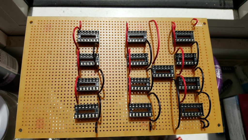
As you can see, the board only has copper on one side. We’re looking at the blank side here. I’ve soldered on a set of IC sockets, and the power rails. This actually took me absolutely ages to do. Soldering the sockets was OK (if you can get them to stay put!), but all those connecting wires really took a lot longer than I expected. Trying to get the wires as short as possible (to make it tidy), but not too short. Trying to bend them into shape. And the wire stripper I bought really wasn’t very good. (But then, what do you expect for £4, I guess?)
I then set about adding the LEDs (with current-limiting resistors), and wiring up some signal connections (purple).
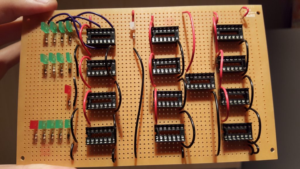
The work you see above took me several hours. Literally an entire day to get this far! The next day, I had another go. It quickly became apparent that I wouldn’t be able to put the chips into their sockets after I plaster the thing with a huge tangle of wires, so some of the chips have been inserted at this point. (The whole reason for the sockets was to prevent my awful soldering skills cooking the chips!)
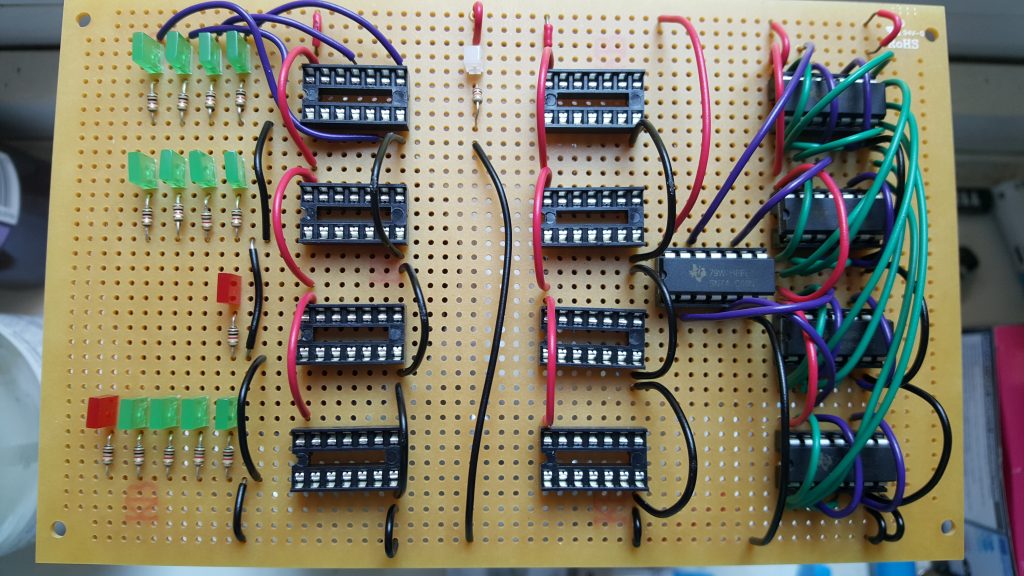
It doesn’t look like much, but this is another day to get this far. By now, I’ve been working on this for two weekends straight, and I’m about one quarter through wiring up a single circuit board that performs a relatively simple function. This is taking way, way longer than I was expecting! I thought this small experiment would only take 20 minutes or so to do. Nope, multiple days of work later, the end is still nowhere in sight.
Eventually, I invested in a second, much more expensive wire stripper. The one I had was pretty much useless. The ones we had at school were fairly lame, but did work better than this. For 10× the price, I got a second wire stripper… that actually works! I mean, this thing is great! Works flawlessly every time. Needless to say, I threw the old one in the bin.
Even with this upgrade, it’s still taking me forever to finish one tiny little board. At this rate, it could take several human lifetimes to get this done!
Adventures with KiCAD
I have clearly underestimated the amount of work to build complex circuits using a prototyping board. (Presumably doing all this with breadboard would have been even worse.) I need to rethink this.
At this point, I started investigating whether it would be possible to have custom circuit boards printed for me. Hackaday did an article about the various contenders for circuit board design. It seems all of them are awful to use, or incredibly expensive, or both. There are several free ones, most of which have artificial limitations to force you to buy the expensive pro version to get any actual work done. After spending a lot of time researching this, I settled on a program called KiCAD.
KiCAD is… awful. I mean, just horrible. It is the most unintuivite thing you’ve ever seen. (What do you expect for a free, open-source program?) Half the commands can only be accessed by keyboard shortcuts. (I.e., there is no way to discover them by looking at the GUI; you just have to know what keys to press.) It’s buggy as hell if you try to do things in an order that it doesn’t like. The schematics it draws look horrible. Really, there’s not much to recommend it.
Well, on the plus side, all of its files are plain text. Which means you can put them in source control — which I immediately did. The KiCAD workflow is that you first have to draw a schematic of the circuit you’re trying to make, and then you have to pointlessly draw it all over again as a circuit board layout. I invested quite a bit of energy into trying to figure out how to avoid this pointless duplication, but ultimately I failed. You can sort-of almost do it, but ultimately it’s futile.
In fact, my first project (to build an adder) is simple enough that the schematic basically just gets in the way. But for later, more complex projects, it would have been pretty much impossible (or at least very, very error-prone) to not have a schematic. So I guess KiCAD forces you to do it that way for a reason. It’s very irritating for trivial board layouts, though.
As I write this, I’ve now built many, many boards using KiCAD, so I’ve generally gotten used to its weirdness and its obtuse interface. I can get stuff done relatively easily because I know what features to avoid. And I’ve managed to build a small parts library containing just the parts I actually use. But damn, does this thing have a learning curve! (And not in a good way.)
Another thing I hadn’t anticipated: It turns out that routine dozens and dozens of wires around a densely packed circuit board is actually quite hard. In the end, it took me multiple attempts to finish the design of my trivial little binary adder. Every time I thought I’d finished, I would go to add another wire, and realise I painted myself into a corner.
Since those early days, I’ve come up with a system: Put all horizontal wires on one side of the board, and all vertical wires on the other side, with an alarming number of vias to connect them. It’s excessive and probably unecessary, but it goes the layout done far faster and easier. Only trouble is the final board ends up looking like Swiss cheese.
Finding a fab
Having laboriously designed by first PCB, now I need to find somebody to actually, you know, print it for me.
I searched and searched for a UK company that will actually print stuff. The only people I found refuse to say what they charge; you have to phone a pushy salesman to get an actual price. Which almost certainly means they’re only interested in printing quantities of thousands, and won’t be at all interested in printing 3 boards just for me.
Hackaday constantly keeps making casual references to “the myriad of companies who will print one-off boards for a dollar each”. I almost want to physically grab the website by the shoulders and shake its brains out, yelling “Where? Where are these mythical companies you speak of?! Tell me what you know!”
It turns out that if you give up on it being a UK company, there actually are quite a lot of people who will print PCBs for you. Some of them will even ship internationally. (Most of them will only ship to America. Because it’s not like any other countries exist, is it?)
I spent a long time researching this. I looked at so, so many websites. I eventually even found a price comparison website for PCBs! (Who knew?) After almost going blind from price comparisons, with great reluctance I eventually went with a company in China. (Eeek!)
It seems several low-cost manufacturers operate out of China; I ultimately went with one called JLCPCB. Their website is pretty much what you’d expect from China; horribly broken English, very slow response time, and rather uninuitive to follow. On the other hand, they will make 5× Eurocard boards for £11 (plus shipping — which isn’t cheap when you’re trying to move something half way around the world). Weirdly, 10× boards is only £15. I guess it’s dominated by setup costs. (I haven’t looked at what it costs for higher quantities.)
For comparison, there’s a much, much nicer website from a German company. The website is far nicer, it’s much more welcoming and friendly, and the documentation is very helpful. Being in Germany, shipping is much faster. Unfortunately, they charge £90 for 3 boards. (!!!) Obviously, that’s far too expensive when every board has roughly a 50% change of being wrong and needing to be redone. Wasting £11 because you forgot to invert a signal is annoying. Wasting £90 is utterly unaccaptable.
Building with PCBs
Nervously, I exported my first design from KiCAD and uploaded it to China. I keep worrying that they’re going to try to steal my IP; I have to keep reminding myself that it’s utterly not worth stealing, so there’s nothing to worry about. The website does at least let you track how many steps of the manufacturing process have been done so far. Eventually they shipped it, and I just had to wait for the goods to arrive in the UK.
(Oh, and pay extra random money to DHL to allow it into the country. Did I mention that part? Yeah, import duty apparently isn’t part of the price they quote.)
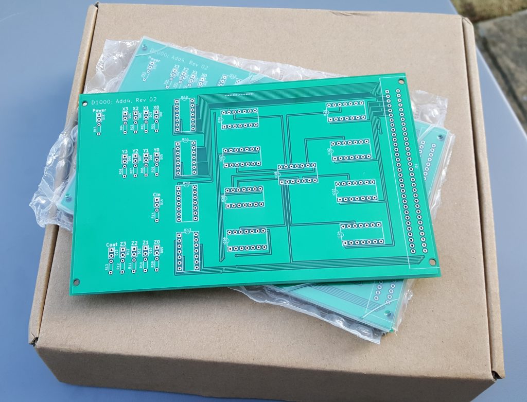
£11 for 5 boards, £30 to ship it half way around the world, and then another £22 for “tax” or whatever DHL is claiming is required. Finaly my boards arrived.
They look really slick. The box is surprisingly heavy, actually. You wouldn’t expect circuit boards to be this heavy. A single board doesn’t weigh much, but apparently when you have half a dozen, it’s surprisingly defty.
So here it is. My first PCB.
I was so excited, I took several pictures at various points during the assembly process.
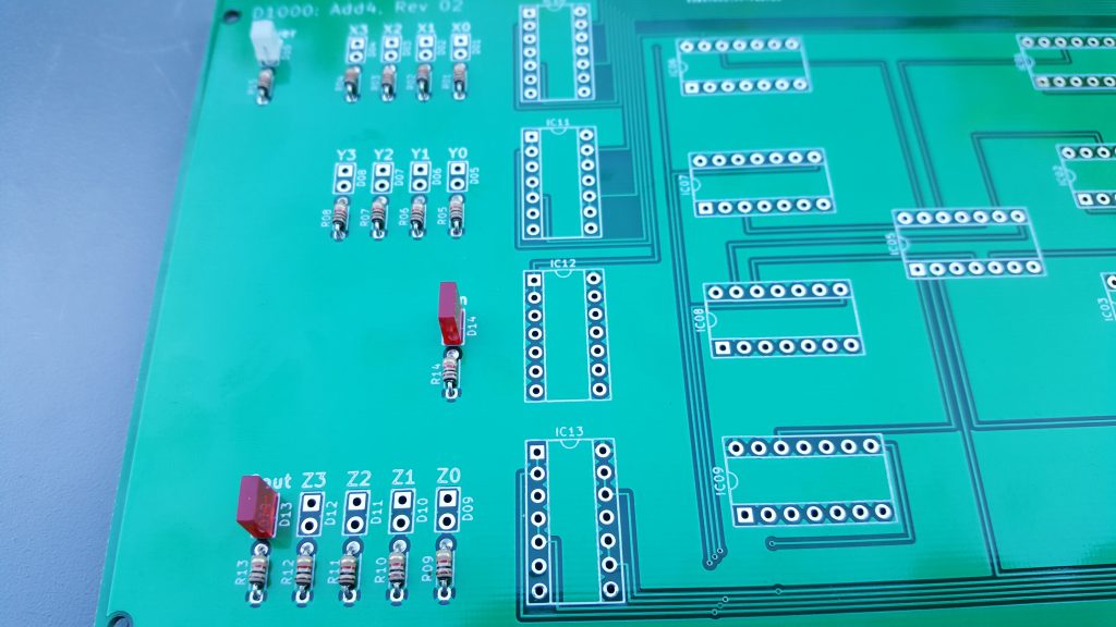
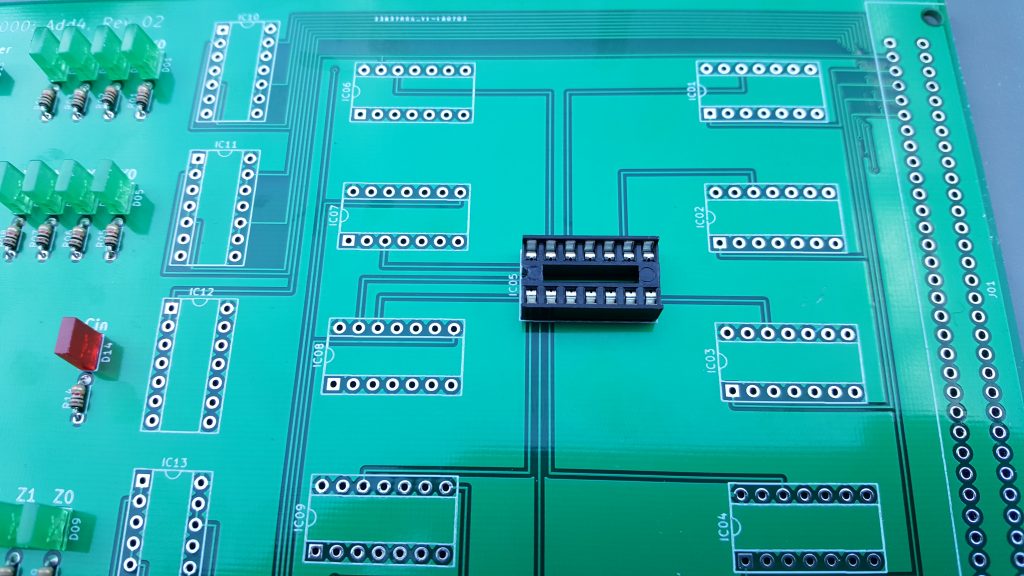
Unlike before, this time it only took me an hour or so (even with all the photography) to complete the whole board. (Although it took multiple days to do the computer-aided design step, so…)

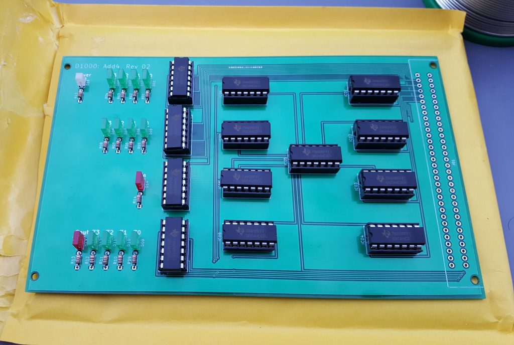
I realised some time after I sent the files off that the plus was misaligned slightly, so there’s no point soldering an expensive plug onto the board. (I don’t have a socket to plug it into anyway.) So I just soldered wires directly to the board for test purposes.
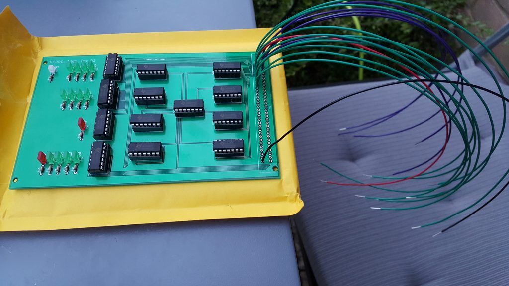
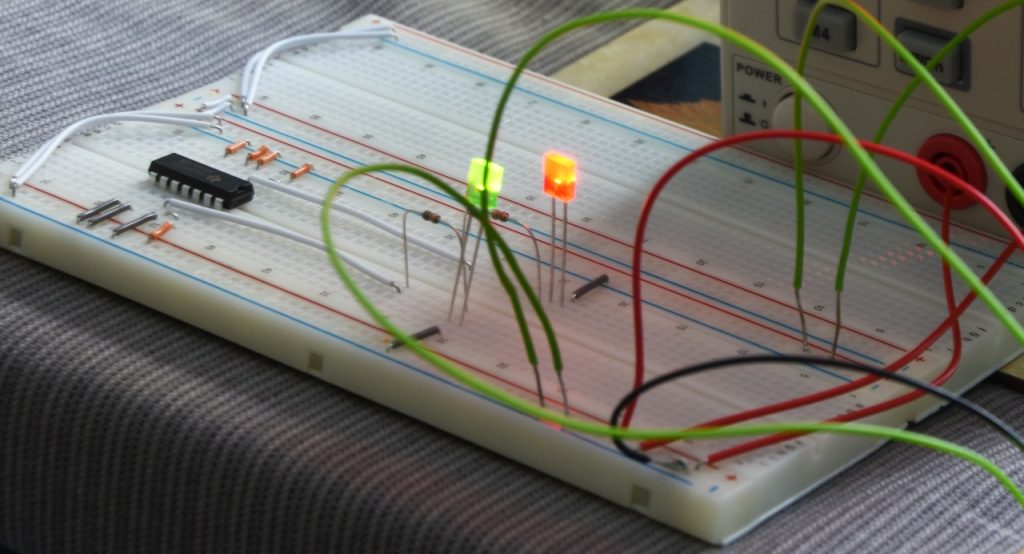
Now, finally, I could go indoors and see if the damned thing actually works!
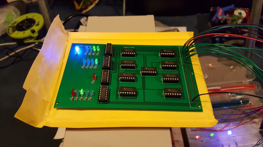
Success! The board works as intended. You can see in the picture, the top row of LEDs shows the first number being added (in this case, 0011). The next row of LEDs is the second number being added (0001). The single red LED below that is a carry-in (to allow chaining multiple adders together). And the bottom row is the total (the red LED is the carry-out signal, which is basically just the 5th digit of the total). You can see that the total comes to 0 0100. In other words, 3 + 1 = 4.
I was so elated. And then this happened:
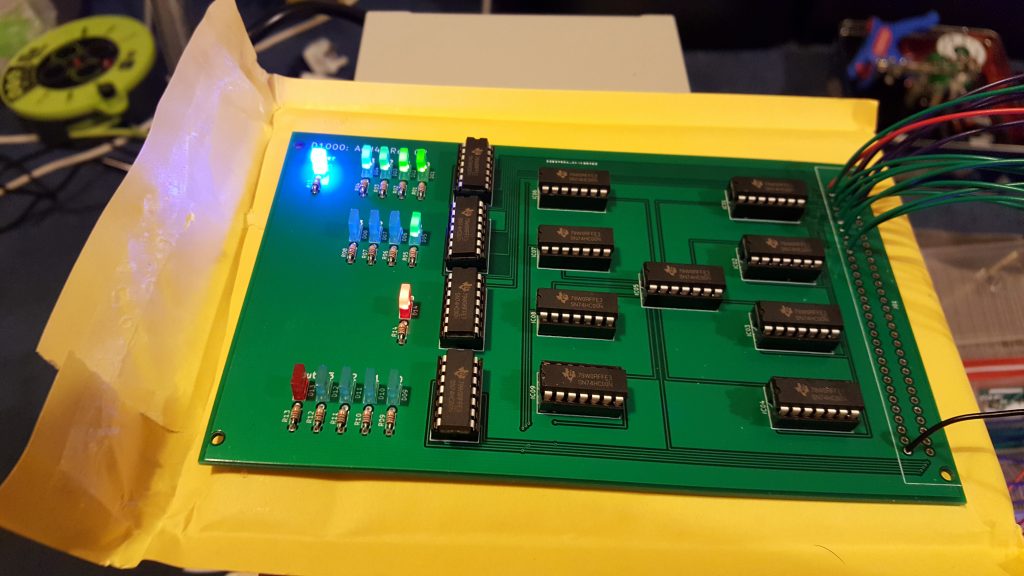
It turns out, the circuit does in fact work perfectly. However, somehow I’ve mixed up the carry-in and carry-out LEDs. Like, they’re literally just in the wrong places on the board. I need to swap them round. Fortunately, it only took about 20 minutes to do that in KiCAD. Unfortunately, I now need to pay another £££ and wait another 2 weeks to get the updated board. (In fairness, I already knew the plug was wrong, so…)
And such as been the process ever since. I now try to order multiple PCBs at once, so I only have to pay shipping once. Sometimes a board works first time. Sometimes I have to make some minor tweak and have a new board printed. It’s always rather galling when that happens, but at £11 per design, it’s not too bad. I’ve paid more money than that for a pizza — and I just ate the pizza!